Table of Contents
Introduction
The CAN Flasher is used to transfer the compiled and linked program to the flash memory of the module from the MRS Applics Studio to MRS Modules.
Applics Studio consists of two different CAN-Flasher tools. The Applics Flasher is the new default Flasher and is suitable for most use cases e.g. during development. It allows you to select the Hardware Interface, Baudrate and the .s19 file.
The CAN Flasher comes with additional features like EEPROM access.
Applics Flasher
This is the new Applics Flasher which includes new features like reading moduledata, search modules, trace window and more. For the future the Applics Flasher will be the main flasher and will be improved within the next releases. Open it inside the Project Tools on the tob bar and select Open Applics Flasher or by pressing F3.

Module Connection Settings
Setup of CAN-Bus and connected interface can be made here.

Baudrate from CAN Settings
CAN_BUS_xBaudrate defined in CAN SettingsDefaultBaudrate selection of Baudrate using predefined values of dropdown listUser-DefCustom Baudrate defined in User-Def Baudrate Window.
Channel
- Select the channel if more than one
CAN Interfaceis available. Lowest channel will be set as default.
Baudrate from CAN Settings
CAN_BUS_xBaudrate defined in CAN SettingsDefaultBaudrate selection of Baudrate using predefined values of dropdown listUser-DefCustom baudrates.


For further information about the regarding CAN-Interfaces and the necessary driver installation please visit the manufacturers website
Refresh - Refresh CAN Interface.
Scan
Searches for all connected participants with the specified baudrate on CAN-Bus.
Search Module
Steps through and searches for all predefined baudrates
Connect/Disconnect
Connect to the channel or disconnect from it. Connection enables the sending of CAN telegrams over the selected channel.
User-Def Baudrate Window
The user-def baudrate window can be opened by clicking on User-Def Baudrate.
Settings Overview
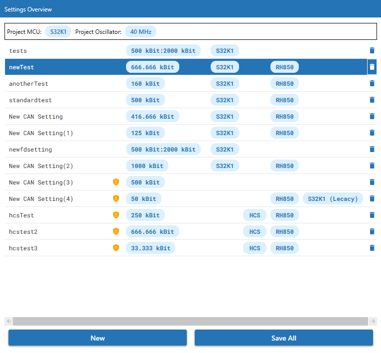
The settings overview contains a list with all user-defined baudrate settings. These settings are shared between projects. A setting can be selected by left-clicking on its row. Once it is selected it can be modified. Each row shows the following from left to right:
NameThe name of the settingWarning IconIndicates that this setting cannot be used for the current project’s moduleBaudrateThe baudrate of the settingMCU TagsIndicate the MCU types that are supported by this setting.Delete IconCan be clicked to delete this setting.
Above the list the current project’s MCU type and oscillator are shown. The oscillator is for Standard CAN and not for CAN FD. There are two buttons below the list:
New
Creates a new setting with a default name.
Save All
Saves all changes to the settings. Non-saved changes are indicated by an asterisk in the window’s title.
Settings Editor
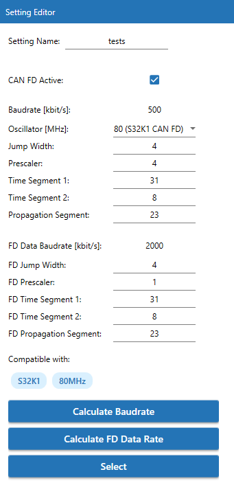
The parameters of the baudrate setting can be modified manually and individually. After a change the displayed baudrate will be updated automatically. The CAN FD Active checkbox can be used to make the setting an FD setting. If checked the FD parameters will be shown. The oscillator can be selected from a drop-down menu. Clicking on the Custom entry will open a dialog window in which a custom oscillator can be entered. Below the parameters the supported MCU types and the settings oscillator is shown.
Calculate Baudrate
Starts the baudrate calculation.
Calculate FD Baudrate
Starts the FD baudrate calculation. Is only visible when CAN FD Active is selected.
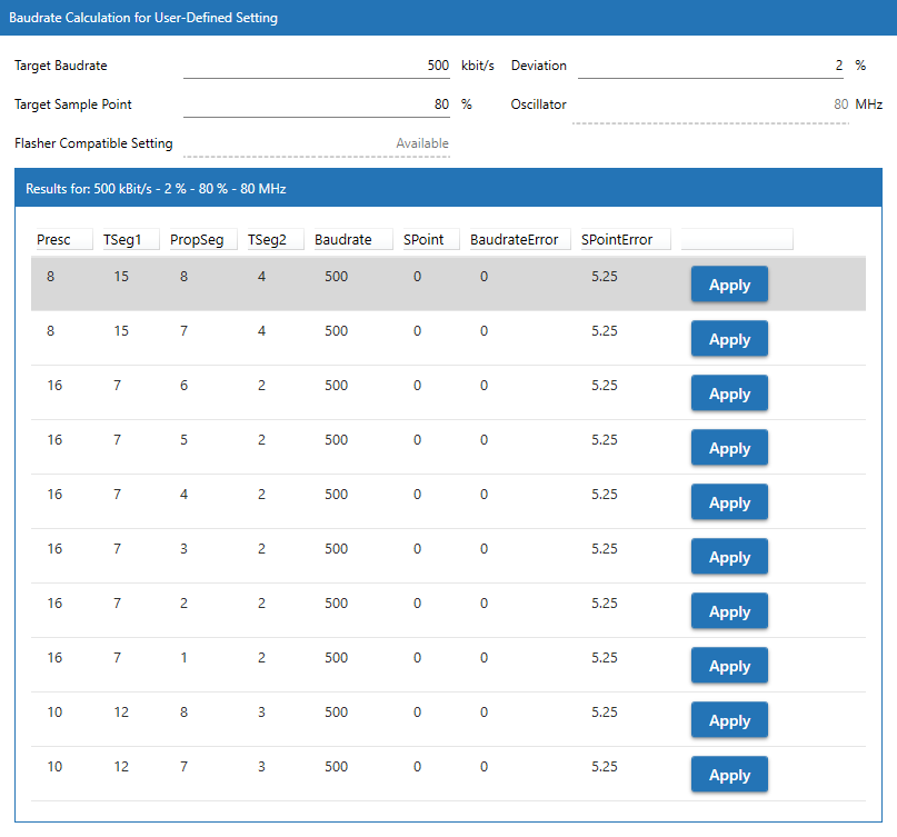
The calculation results will be displayed in the Baudrate Calculation.
Select
All settings will be saved. Then the selected baudrate setting will be applied to Applics Flasher or the Can Setting in the CAN Settings.
Baudrate Calculation
Enter a target baudrate, a samplepoint and the maximum allowed deviation to receive a list of fitting baudrate settings. The oscillator clock is determined automatically. The calculation has to first be initiated by pressing Calculate Baudrate (or Calculate FD Baudrate) in the Settings Editor. Clicking on Apply will overwrite the currently selected setting (see Settings Overview for selection) with the setting from the result list.
Advanced Settings
Clicking on Advanced Settings will expand them.
Fast Mode Increases the flashing speed significantly. With the default value ‘Auto’ all modules that support ‘Fast Mode’ wil use it. Fast Mode can be explicitly deactivated and activated. If you notice problems during flashing, try to disable this function and try again.
Wait For Module Start Extends the wait time during Scan or Search Module until the module was found or until the time that was set here passed.
Ignore Scripts Disables the auto-start for scripts embedded inside the .s19 file.

Feedback and further information about the Fast Mode can be requested via support@mrs-electronic.com
Flasher Tab
Found CAN Modules
All connected MRS-Controllers are shown inside this window, as well as some module specific data like the modulname and its serialnumber.

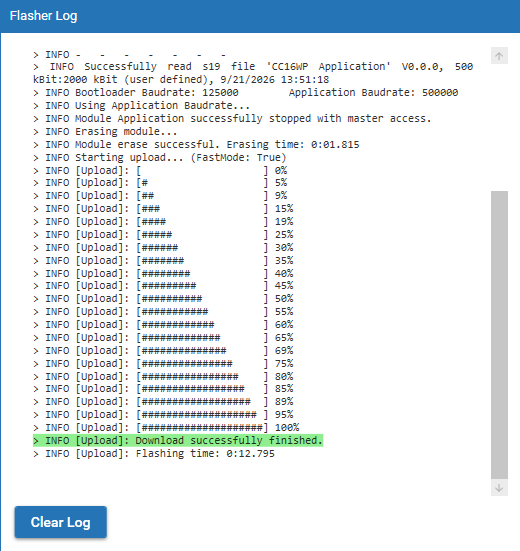
Further information about the flash progress and state or error messages are monitored in the Flasher Log window.
Firmware & Module Actions
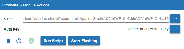
Allows the selection of an .s19 file and and Authentication Key. It is also possible to start/stop the application or restart the module using the icon buttons Start App, Stop App or Restart Module.
Run Script
Opens a file dialog to choose an MRS script. After a script file has been selected the script is automatically executed.
Start Flashing
Flash process is described here Flash Project
Flasher Log
Further information about the flash progress or error messages are monitored in the Flasher Log window. This content can be cleared by Clear Log.
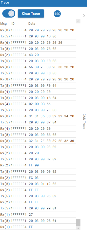
CAN Trace
Displays CAN traffic which can be enabled and disabled using the slider on the upper left. The trace can be collapsed and expanded by pressing on the right-most part of it. By default it is collapsed.
Clear Trace Removes all messages from the trace.
REC Starts the recording of the messages on the trace. Pressing it again will show a dialog window to select a save location.
CAN Flasher
Installation of MRS Developers Studio and related drivers are necessary to use the CAN Flasher.
Purpose of Can Flasher is intended to be more flexible and offers the possibility to get detailed information for development reasons. Main features are listed below:
ScanModule on selected BaudrateSearch ModuleSteps through all predefined Baudrates- Flash s.19-file with
DownloadorReflash last s19-file - Log Window: Shows state and error during scan and download process
- Trace Window:
CAN Trace>>Displays CAN traffic Module testPossibility to display or send specified Datapoints using a symbol fileModule data- Displays specific data of selected module
Read all data from module - Possibility to change Bootloader CAN ID
Write CAN ID, Bootloader BaudrateWrite baudrateand Module nameWrite module name Start programStop programStart and stop applicationRestart moduleModule will be restarted
- Displays specific data of selected module


Take care while changing module data, especially the Bootloader CAN ID. Further information about the Module data can be requested via support@mrs-electronic.com