Table of Contents
Introduction
This chapter will give you an overview and information on how to configure CAN Bus communication. There are different possibilities to setup a CAN Bus communication with MRS Modules.

CAN Settings
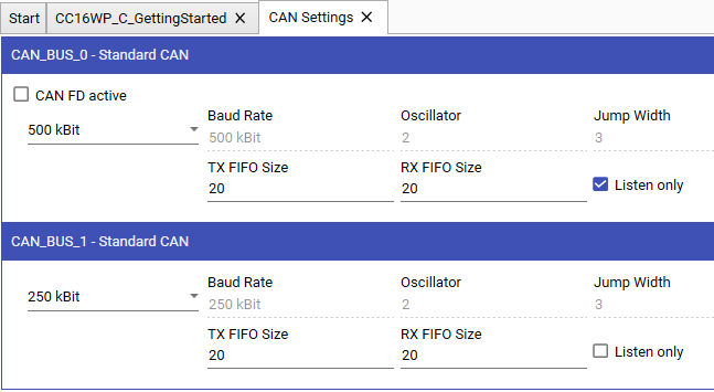
Here you can select the baudrate for the CAN Bus. The new baudrate will be used by the module after the first build and flash is completed.
Baudrate
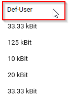
You can select from a list of predefined baudrates or define your own baudrate.


The baudrate of new modules by default is 125 kbits/s.
Custom Baudrate
If the required baudrate ist not available, it is possible to set a custom defined baudrate.
To set your own custom Baudrate, choose Def-User from the baudrate drop down list.

Baudrates are defined by the following Parameters:

- Jump Width
- Prescaler
- Time Segment 1
- Time Segment 2
- Propagation Segment
If you already have all the parameters available, simply enter them in their respective input field.

 Be careful as the baudrate parameters depend on the external oscillator frequency on the hardware. For more information see the corresponding datasheet.
If a user defined baudrate is choosen for CAN Bus 0, the bootloader baudrate is set to the last used predefined baudrate.


Since Applics / BSW V4.16.0, we changed the registers used to hold the timesegments which increased the register size from 3 to 5 bit. Since the sample point position is calculated as
Sample point = ((Time_Segment_1 + 1) / (Time_Segment_2 + Time_Segment_1 + 1)) * 100
, the biggest possible sample point previously was
((7 + 1) / (2 + 7 + 1)) * 100 = 80%
with 7 being the biggest possible value for TSEG1 and 2 being the lowest possible value for TSEG2.
With the new changes, the biggest sample point can now be calculated as
((31 + 1) / (2 + 31 + 1)) * 100 ~ 94%.
with 31 being the biggest possible value for TSEG1. Additionaly, the resolution of possible sample points was greatly improved.
Custom Baudrate Calculator
If you wish to use a specific baudrate, Applics is able to calculate the above mentioned baudrate parameters. For this, press the Calculate button underneath the baudrate combobox selector.

Set the Target Baudrate to the desired baudrate. Applics will suggest possible baudrate parameters.

Aside from the baudrate, you can also set the maximum allowed Deviation from the target baudrate. Applics will only display baudrate parameter solutions that fall within that allowed range. The default value is two percent.
The last parameter is the Target Sample Point in percent. It defines at which point in each bit period the CAN controller looks at the state of bus and determines if it is 0 or 1. The default is 80%.
FIFO
You can also alter the TX/RX FIFO Size in the CAN settings if you need to (most likely you don't!). This determines how many messages for send (Tx) and receive (Rx) can be buffered by the basic software of the module. This can be needed in special circumstances e.g.:
- high bus load with especially in gateway applications
- you notice CAN Frames are lost or missing
Listen Only
The module enters the listen only mode for the selected CAN interface by activating the checkbox Listen only. In this mode, the transmission is disabled, the error counters are frozen, and the module operates in a CAN Error Passive mode. Only messages acknowledged by another CAN station will be received.


Listen Only Mode is supported from Basic Software Version 3.10.0.
CAN DB Editor
For CAN bus communication it is necessary to define CAN Telegrams and CAN Datapoints with the CAN DB Editor. Click Open CAN DB Editor (F2) to open it. The CAN DB Editor is divided into two parts: the CAN Telegramms and the CAN Datapoints.


You can also import and export this data to common formats like .sym and .dbc.
Create CAN Block
A CAN Telegramm / CAN Block is a CAN Frame which is defined by a 11- or 29-Bit Identifier, a name and the payload from 0 to 8 bytes. Each CAN Telegramm can be assigned to a specific CAN bus and configured for receiving or sending.


For more information about the columns place the mouse button over the symbol and the description appears.
Create CAN Datapoints
A CAN Data Point is variable inside a CAN Block, which is defined by a number of bits within a 8 Byte array. It is possible to have multiple CAN data points within the same CAN block as long as you have bits to be attributed.
CAN Multiplexer
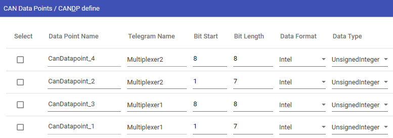
To transmit different data sets within a CAN-Frame with the same CAN-ID, so called multiplexer can be defined. Multiplexers are specially bits in the data bytes whose content identifies the meaning of the remaining data bytes.
Definition and layout of a multiplexer is described in the following example:


Graphical layout visualization of the bit positions inside a dataframe including multiplexer bits:


Export and Import Database
Option to Import or Export the defied CAN Telegrams and CAN Data Points are saved in database symbol-file. This database can be imported and exported to use it by an external software tool.
Export Sym
After definition of Telegrams and Datapoints a symbol-file can be exported Export Sym. This can be used by other tools e.g "PCAN-Explorer".
During the export process the window Sym Export will appear. Here it is possible to change the transmit direction by selecting Yes or No. This can be useful when working with tools like "PCAN-Explorer.
Import Sym and Dbc
Using a predefined symbol- or dbc-File is also supported. The import process can be started with the button Import Sym/Dbc. Import needs to be confirmed with Check and Save.
CAN Gateway
Click the button Open CAN Gateway to open the gateway settings. Now the Gateway can configured by activating the checkbox for the Gateway Inputs and Gateway Outputs.
This example will send all messages received on CAN Bus 0 without any changes directly to CAN Bus 1.

